4.4 THRUST CHAMBER COOLING
Techniques and Their Selection
Because of the high combustion temperatures ( to ) and the high heat transfer rates from the hot gases to the chamber wall ( 0.5 to ), thrust chamber cooling becomes a major design consideration. For shortduration operation (up to a few seconds), uncooled chamber walls can be used. In this case, the heat can be absorbed by the sufficiently heavy chamber wall material which acts as a heat sink, before the wall temperature rises to the failure level. For most longer duration applications, a steady-state chamber cooling system has to be employed. One or a combination of the following chamber cooling techniques is often used:
- Regenerative cooling.-Regenerative cooling is the most widely applied method and utilizes one or possibly both of the propellants, fed through passages in the thrust chamber wall for cooling, before they are injected into the combustion chamber. (See par. 4.1 and fig. 4-1.)
- Dump cooling.-With this principle, a small percentage of the propellant, such as the hydrogen in a engine, is fed through passages in the thrust chamber wall for cooling and subsequently dumped overboard through openings at the rear end of the nozzle skirt. Because of inherent problems, this method has only limited application.
- Film cooling.-Here, exposed chamber wall surfaces are protected from excessive heat with a thin film of coolant or propellant which is introduced through manifolded orifices in the chamber wall near the injector, and usually in several more planes toward the throat. The method has been widely used, particularly for high heat fluxes, either alone or in combination with regenerative cooling.
- Transpiration cooling.-Transpiration cooling is accomplished by introducing a coolant (either gaseous or liquid propellants) through porous chamber walls at a rate sufficient to maintain the desired combustion gas side chamber wall temperature. This method is essentially a special type of film cooling and has been widely used.
- Ablative cooling.-In this process a sacrifice of combustion-chamber gas-side wall material is made by melting and subsequently vaporizing it to dissipate heat. As a result, relatively cool gases flow over the wall surface, thus creating a cooler boundary layer, assisting the cooling process. Ablative cooling has been used in numerous designs, initially mainly for solid propellant systems, but later equally successfully for low , pressure-fed liquid systems.
- Radiation cooling.-With this method, heat is radiated away from the surface of the outer thrust chamber wall. It has been successfully applied to low heat flux regions, such as nozzle extensions.
The selection of the best cooling method for a given thrust chamber depends on many design considerations. There are no simple-and-fast rules. However, the following are the main factors which influence the selected design approaches:
- Propellants. -The properties of the combustion products, such as temperature, specific heat, specific weight, viscosity, etc., have a direct bearing on the heat transfer rate and in turn affect the chamber cooling requirements and methods. The cooling properties of the propellants and their relative flow rate decide whether they are suitable or sufficient for regenerative or film cooling. Therefore, in evaluating a chamber cooling system, the propellants involved will be one of the primary design considerations.
- Chamber pressure.-High chamber pressure is linked with higher combustion gas mass flow rates per unit area of chamber cross section and thus raises the heat transfer rate. Combined regenerative and film-cooling methods are usually employed for the stringent requirement of higher chamber pressure applications.
- Propellant feed system.-The type of propellant feed used in an engine system determines the pressure budget for the system. In a turbopump-fed engine system, more pressure drop is usually available for chamber cooling. The availability of this pressure drop permits the use of regenerative cooling which requires propellant pressure sufficient to force the coolant through the cooling passage before entering the injector. A pressurized-gas-fed engine system usually has more stringent pressure limitations and operates on relatively low chamber pressures. This suggests the application of film, ablative, or radiation cooling.
- Thrust chamber configuration.-The geometric shape of the chamber affects local combustion gas mass flow rates and wall surface areas to be cooled. This influences the choice of cooling method. It can also limit the design arrangements for regeneratively cooled tubular wall thrust chambers.
- Thrust chamber construction material.-The properties of the thrust chamber materials will affect the cooling system design profoundly. Strength at elevated temperature, combined with heat conductivity properties of a metal, will determine suitability for regenerative cooling systems. For film-cooled chambers higher allowable material working temperatures are desired to reduce heat transfer rates and thus film coolant flow rates. The application of radiationcooling to a chamber depends largely on the availability of high temperature ( and up) refractory alloys. The success of ablative cooling depends entirely on the availability of suitable composite plastic materials.
In practice, the design of thrust chamber cooling systems is a major link in the complete engine system design. It cannot be treated independently, without due consideration of other engine system aspects. For instance, optimization of the chamber pressure value for a highperformance engine system is largely limited by the capacity and efficiency of the chamber cooling system. In turn, chamber pressure will affect other design parameters such as nozzle expansion area ratio, propellant feed pressure, and weight. Because of the complex interrelation between these factors, the complete analysis of chamber cooling systems is a specialized field and requires thorough knowledge of heat transfer, fluid mechanics, thermodynamics, and thermal stresses. The engine system designer, therefore, will enlist the services of heat transfer specialists.
Gas-Side Heat Transfer
One of the primary steps in the design of a thrust chamber cooling system is the analysis of the heat transfer from the combustion gases to the chamber walls (gas-side heat transfer). Because of the very high surface velocity of the gases along the chamber walls, the heat transfer occurs mainly through forced convection; i.e., through the transfer of heat energy resulting from the relative motion of different parts of a fluid. Before the gases can transfer heat to the wall, the heat energy must pass through a layer of stagnant gas along the wall, called the boundary layer.
The basic correlation for this complicated convective heat transfer can be expressed by the following equation:
where Heat flux or heat transferred across the stagnant gas film per unit surface area per unit time, Gas-side heat transfer coefficient, Btu/ in -sec-deg F Adiabatic wall temperature of the gas, turbulent boundary layer recovery factor (ranging from 0.90 to 0.98) Hot-gas-side local chamber-wall temperature, deg R The determination of the gas-side heat transfer coefficient is a rather complex problem. The convection phenomenon as it occurs in rocket thrust chambers eludes complete understanding. Attempts to compare analytical results with experimental heat-transfer data obtained on rocket thrust chambers have often shown disagreement. The differences are largely attributed to the initial assumptions for analytical calculations. For example, there is good evidence that oxidizing and reducing atmospheres covering a wide range of temperature exist locally in the combustion product gases within the thrust chamber, because of the imperfect mixing of the propellants at the injector face. This results in deviations from calculations based on the assumption of homogeneous product gases.
However, it has been established by experiment that the heat-transfer coefficient is pre- dominantly influenced by the mass velocity or the mass flow rate per unit area of the gas, subject to the exponent 0.8 . In comparison, all other factors are relatively minor. A rough approximation of can thus be expressed by the following equation:
where Free stream value of local gas density, lb/cu in Free stream value of local gas velocity, in/sec Thus, under normal circumstances, the heattransfer coefficient varies with the chamber pressure to the 0.8 power and throughout a given chamber inversely with the local chamber diameter to an exponent of 1.8 .
Based on experience with turbulent boundary layers, some relatively simple correlations for the calculation of the gas-side heat-transfer coefficient have been developed. A much-used form is that credited to Colburn
where Nusselt number Dimensionless constant Re Reynolds number Free stream velocity, in/sec Prandtl number Hydraulic diameter, in Gas thermal conductivity, deg F/in Viscosity, lb/in sec Specific heat at constant pressure, or as Bartz has shown where
Area under consideration along chamber axis The value of can be evaluated in terms of nozzle stagnation temperature, local gas-side chamber wall temperature, and local Mach number.
values of for various and , as computed by Bartz, are shown in figure 4-24.
If and data are not available for particular combustion gas mixtures, the following equations can be used for approximate results:
where =temperature of gas mixture, Equations (4-13), (4-14), (4-15), and (4-16) can be used to calculate the approximate values along the thrust chamber walls. However, the calculated values can be expected to be lower than the actual ones if the following conditions exist:
 Figure 4-24.-Values of correction factor for property variation across boundary layer.
(1) A substantial fraction of the combustion gases are strong radiators. (2) There is substantial dissociation, with subsequent recombination near the wall. (3) There are strong high-frequency flow instabilities. The calculated values may be higher than the actual ones, because of the following: (1) The combustion reactions may not be completed in the chamber. (2) The combustion gases may deposit solids on the chamber walls, which act as insulators. In certain propellant combinations, the combustion products contain small amounts of solid particles. These solids tend to deposit on the chamber walls, and form a rather effective insulating layer. A quantitative evaluation of the insulation effectiveness of this layer, necessary for correct heat transfer calculations, has been accomplished only experimentally.
In the case of the combination, carbon solids are deposited on the chamber walls. After a firing, the carbon gives the interior of the thrust chamber the appearance of being freshly painted black. The outer surface of the carbon appears sooty and can easily be removed by light rubbing. Underneath the exterior soot layer is a harder, graphitelike layer which can also be removed, but is more tenacious. This carbon deposit significantly increases the gas-side thermal resistance. The temperature of the carbon deposit at the hot gas-side interface approaches the gas temperature as the carbon thickness increases.
The values of the thermal resistance of the carbon deposit based on actual experimental testing results of a thrust chamber burning are shown in figure 4-25.
For the heat transfer calculation of the gasside heat transfer with solid deposit on chamber walls, the following equations can be used
where overall gas-side thermal conductance, Btu/in -sec-deg F
 Figure 4-25.-Thermal resistance of carbon deposit on chamber walls , mixture ratio .
where thermal resistance caused by the solid deposit, in -sec-deg F/Btu
When there is no solid deposit, and , and equation (4-10) is used for heat transfer calculations.
Sample Calculation (4-3)
Determine the approximate design gas-side overall thermal conductance in the combustion chamber, at the throat, and at the exit nozzle point of , for the regeneratively cooled thrust chambers on the A-1 and A-2 stage engines.
Solution
(a) A-1 Stage Engine
First, let us consider equation (4-13). The combustion reactions are assumed to be homogeneous and complete. From figure the following values are derived for the chamber product gases, for at and a mixture ratio of 2.35 :
The design
(See eq. 1-32a and 1-41). From sample calculation (4-1):
From sample calculation (4-2):
Mean radius of the throat contour
From equation (4-15):
From equation (4-16):
From equation (4-13):
Since the carbon deposit temperature approaches the gas temperature, a ( ) value of 0.8 is used to determine the values from figure 4-24 ( ).
At the combustion chamber:
At the throat:
At the exit nozzle point of
The experimental data of figure 4-25 can be used to determine the values of thermal resistance , for the carbon deposit. The thermal resistances are , and for points at the combustion chamber, the throat, and the exit nozzle area ratio of .
Substitute into the equation (4-18); at the combustion chamber
at the throat
At the exit nozzle of .
(b) A-2 Stage Engine
Again, the combustion reactions are assumed to be homegeneous and complete. From figure 4-4, the following values are derived for the chamber product gases, for at and a mixture ratio of 5.22 :
The design Theoretical
From sample calculation (4-1):
From figure 4-21:
Mean radius of the throat contour
From equation (4-15):
From equation (4-16):
From equation (4-13):
Since there is no solid deposit on the chamber walls, an average gas-side wall temperature of is assumed, and a ( ) value of (1500/5740) or 0.26 is used to determine the values from figure 4-24.
At the combustion chamber:
At the throat:
At the exit nozzle point of :
Regenerative Cooling
The heat transfer in a regeneratively cooled chamber can be described as the heat flow between two moving fluids, through a multilayer partition. Figure 4-26 shows this process schematically. The general steady-state correlation of heat transfer from the combustion gases through the layers, which include the metal chamber walls, to the coolant can be expressed by the following equations:
 Figure 4-26.-Heat transfer schematic for regenerative cooling.
where
The bulk temperature of the coolant increases from the point of entry until it leaves the cooling passages, as a function of the heat absorbed, and of the coolant flow rate. Proper balance of these parameters, to maintain the chamber walls at temperatures below those at which failure might occur because of melting or stress, is one of the major criteria for the design of regeneratively cooled thrust chambers. For metals commonly used in thrust-chamber walls, such as stainless steel, nickel, and Inconel, the limiting hot-gas-side wall temperature is around . The resultant differences between combustion gas temperature and wall temperature range from to .
Assume a station in the thrust chamber with gas temperature and coolant bulk temperature . Referring to equation 4-21, it is seen that the heat flux , which must be the same through all layers, is a function of the temperatures, and of overall heat transfer coefficient . The value of is composed of the individual coefficients for the boundary layers and the chamber metal wall (eq. 4-22). The smaller , the smaller is . However, it is one of the major design goals to keep coefficient low, but heat transfer coefficient and conductivity high, in relation to . Since the temperature differentials are inversely proportional to the heat-transfer coefficients of the heat flow paths, the temperature drop will then be steepest between hot gas and inner chamber wall. The effect is analogous to voltage drops along resistors in electrical circuits.
It is noted that the heat absorbed by the propellant used for regenerative cooling raises temperature of the propellant, and thus the energy level before it is injected into the combustion chamber. However, this effect on overall engine performance is slight, the gain usually being less than 1 percent. On the other hand, regenerative cooling with attendant pressure losses requiring additional turbopump power or higher gas pressurization levels imposes a performance penalty.
Coolant Side Heat Transfer
The coolant side heat-transfer coefficient is influenced by many factors. At the high heat fluxes and temperatures encountered in thrust chamber operation, the propellants used for cooling may become corrosive, may decompose or deposit impurities upon the heated surface, thereby reducing cooling effectiveness. It is impossible to calculate the values under these conditions without experimental data.
The characteristics of coolant side heat transfer depend largely on the coolant pressure and coolant side wall temperature. In figure 4-27, the heat flux is plotted versus wall temperature for a constant coolant pressure, bulk temperature, and flow velocity. Curve A indicates the behavior of heat transfer at coolant pressures below critical. Line segment represents the heat transfer without boiling when the wall temperature is below the saturation temperature of the coolant corresponding to the fluid pressure. As the wall temperature at exceeds the saturation temperature by a certain margin ( to ), bubbles will form within the coolant layer close to the wall. The bubbles grow continuously out into the colder liquid stream until condensation at the vapor to liquid surface begins to exceed the rate of vaporization at the base of the vapor bubble, whereupon the bubbles start to collapse. This process, which occurs at high frequencies, is described as "nucleate boiling." It substantially increases the heat-transfer coefficient, resulting in little increase in wall temperature for a wide range of heat fluxes. The heat transfer with nucleate boiling is represented by line . At , further increase in the heat flux abruptly leads to such a dense bubble population that the bubbles combine into a vapor film with an attendant large decrease in heat-transfer coefficient. The region of heat transfer with film boiling is represented by line . The resulting increase in
 Figure 4-27.-Heat flux versus coolant side wall temperature of typical propellant in various heat transfer regions.
wall temperature is so high that failure of the wall material often occurs. The heat flux at is defined as the upper limit of nucleate boiling of the coolant , which therefore should be used as the design limit for a regenerative cooling system.
Curve B indicates the heat transfer behavior of a coolant above critical pressure. Since no boiling can occur, the wall temperature continually increases with increasing heat flux. Line represents the heat-transfer region, when the wall temperature is below the coolant critical temperature. The heat-transfer coefficient remains essentially constant. As the wall temperature reaches the critical temperature and higher, a gradual transition to a stable supercritical vapor-film boundary layer begins, which results in somewhat lower heat-transfer coefficients. Line represents the heat transfer in this region. Wall failure temperatures are usually reached at lower temperatures when the coolant is above the critical pressure than when it is below it. Where possible, a coolant operating pressure between 0.3 to 0.7 of critical pressure should be used to take advantage of the high heat-transfer coefficients available with nucleate boiling. However, in most systems, particularly those which are fed from a turbopump, the cooling jacket pressure, which is equal to or larger than the sum of chamber pressure and injection pressure, is supercritical. For the nonboiling subcritical temperature regions of both, subcritical and supercritical coolant pressures ( and in fig. 4-27), the relationship between wall temperature and heat flux, which depends on the heat transfer coefficient , can be predicted with sufficient accuracy for design purposes with the help of the Sieder-Tate equation (eq. 4-23) for turbulent heat transfer to liquids flowing in channels:
where
$C_{1}=$ a constant (different values for various
    coolants)
$N u=$ Nusselt number $=h_{c} d / k$
$\operatorname{Re}=$ Reynolds number $=\rho V_{\text {co }} d / \mu$
$P_{r}=$ Prandtl number $=\mu C_{p} / k$
$\mu \quad=$ coolant viscosity at bulk temperature
$\mu_{w}=$ coolant viscosity at coolant sidewall
    temperature
d = coolant passage hydraulic diameter, in coolant thermal conductivity, deg F/in coolant density, coolant velocity, in/sec coolant specific heat at constant pres- sure, Btu/lb-deg F
The heat flux at the upper limit of nucleate boiling can be estimated from
where
| constant, its value depending on | |
|---|---|
| coolant used | |
| heat flux without nucleate boiling, | |
| Btu | |
| coolant pressure, psia | |
| G | coolant maximum flow rate per |
| unit area, |
When the heat is transferred through a vaporfilm boundary layer (coolant at supercritical pressure and temperature, region in fig. 4-27), the coolant-side heat-transfer coefficient can be estimated from
where
The bulk temperature of most coolants should be kept below the critical temperature, since the vapor-film heat-transfer coefficient would be too low to cool the wall effectively. The cooling capacity of the liquid-state regenerative coolant system can be estimated by
 Figure 4-28.-Coaxial shell tarust chamber cutaway. Note overheated and burnt-through spot on chamber wall.
where coolant capacity, B'u/sec coolant mass flow rate, coolant specific heat at constant pressure, Btu/lb-deg F colant critical temperature, deg R coolant inlet temperature, deg R The allowed value of the total chamber wall gas heat-transfer rate should be kept below by a safe margin ( ).
However, there is no such limitation for hydrogen when used as a coolant. Hydrogen has excellent heat-transfer characteristics with a reasonably high heat-transfer coeffic ent even in the supercritical pressure and temperature region. Usually liquid hydrogen enters the chamber coolant passage under superctitical pressure and reaches supercritical temperature a short distance from the inlet.
The coolant passage areas at various points along the chamber walls are designed to uaintain the proper coolant velocity dictated by the heattransfer coefficients determined by the heat- transfer calculation. There are several basic design approaches for regenerative-cooled thrust chambers. Axial-flow cooling jackets, made up of tubes, are used in the design of large thrust chambers ( 3000 pounds of thrust and up); coay:ial shells separated by helical ribs or wires are typical of the smaller thrust chamber designs. Figure 4-1 shows a large regenerative cooled tubular wall thruse chamber. Figure 4-28 represents a typical coaxial shell design for a smaller thrust chamber.
In this design, the coolant passage is defined as the rectangular area between inner and outer shell and two adjacent ribs, which are wrapped helically around the inner shell or liner.
Tubular Wall Thrust Chamber Design
In the design of tubular wall thrust chambers, the number of coolant tubes required is a function of the chamber geometry, the coolant weight flow rate per unit tube c.ea, the maximum allowable tube wall stress, and fabrication considerations. The critical cooling region is near the throat where the heat flux is highest. It is this regicn, then, which determines the number of tubes required for a given coclant flow rate. For easier fabrication and lower stress, tube cross sections of circuiar shape are preferred. However, other shapes are often used to meet certain flow-area requirements. The stress analysis of the tubes is based upon three primary considerations: the hoop stress caused by coolan pressure, the thermal stress caused by temperatura gradient across the tube section and the wall, and the bending stress caused by distortion induced by the pressure differential between adjacent tuies (if any) or by other effects such as discontinuities. The tube design stress is based on the combined stress from the above three considerations. It has been found that the maximum combined stress will occur at the throat region.
As shown in figure 4-29, the maximum combined tangential stresses of the circular-tube will be at section A-A and can be expressed by
where comrined tangential tensile stress, heat flux, tube radius, in = tube wall thickness, in coolant pressure, combustion gas pressure, modulus of elasticity of tube wall material, a =thermal expansion coefficient of tube wall material, in/in-deg F thermal conductivity of tube wall material, Btu/in -sec-deg F/in Poisson's ratio of tube wall material bending moment caused by discontinuity, in-lb/in (no effect of pressure differential between adjacent tubes for circular tube design) Since the combustion-gas-side portion of the tube (zone I) has a much higher mean temperature than that of the back side tube portion and chamber outer shell (zone II), the thermal expansion of zone I will be restrained by zone II. Because of the considerably greater mass of zone II, thermal inelastic buckling is induced under certain conditions, in zone I, in the longitudinal direction. The longitudinal thermal stress can be estimated by
where longitudinal thermal stress, mean temperature difference between zone I and zone II, deg F should be kept at a level not higher than , below. The critical stress for longitudinal inelastic buckling on zone I can be estimated by
where critical stress for longitudinal inelastic buckling in zone I, lb/in tangential modulus of elasticity at wall temperature, tangential modulus of elasticity from compression stress-strain curve, at wall temperature, An elongated cross section tube design is shown in figure 4-30. Equations (4-27), (4-28), and (4-29) can be also applied to calculate the stresses for this design. Here again the maximum combined stress is at section . The bending moment at section , should take into consideration the pressure differential (if any) between adjacent tubes.
 THRUST CHAMBER
Figure 4-29.-Circular tube wall of regeneratively cooled thrust chamber.
 Figure 4-30.-Elongated tube wall of regeneratively cooled thrust chamber.
where
Substituting equation (4-30) into equation (4-27), the maximum stress of the elongated tube can be calculated.
The working loads induced in a regenerative tubular wall chamber by the chamber pressure are designed to be absorbed by a chamber jacket or tension bands wrapped around the tube bundle.
Coaxial Shell Thrust Chamber Design
In a coaxial-shell-type thrust chamber as shown in figure 4-28, the outer shell is subjected only to the hoop stress induced by the coolant pressure. The inner shell, however, is subjected to the combination of compressive stress caused by the pressure differential between the coolant and combustion gases, and of the thermal stress caused by the temperature gradient across the wall. The maximum stress occurs at the inner-wall surface of the inner shell and can be calculated from the following equation.
where
Pressure Drop in Cooling Passages
It is desirable to design a cooling passage with minimum pressure drop. Abrupt change of flow direction and sudden expansion or contraction of flow areas should be avoided. The inner surface of cooling passages should be smooth and clean. The pressure drop in a cooling passage can be treated as that in a hydraulic conduit and be calculated accordingly.
where
Sample Calculation (4-4)
Determine the cooling passage and the tube design at the throat for the thrust chambers of the A-1 and A-2 stage engines.
Solution
(a) A-1 Stage Engine
The fuel, RP-1, is used as the coolant. Since the cooling requirement is most stringent at the throat, the tube design for this station will serve as the starting point for the entire chamber. For high strength, Inconel is chosen as the tube material. Based on experimental test results which showed good solid carbon deposits, design values not exceeding or may be permitted for gas-side tube-wall temperature. Specifically for the throat region, a value of is taken. Using the results of sample calculation 4-3, the value for the adiabatic wall temperature can be calculated by multiplying by the estimated stagnation recovery factor of . From the same caiculation, the overall gas-side thermal conductance at the throat region is . Substitute into equation (4-10), to obtain the heat flux at the throat:
From supplier's specifications, the following average data are obtained for Inconel at : Coefficient for thermal expansion, ; modulus of elasticity, ; thermal conductivity, ; Poisson's ratio, .
A circular tube configuration with an internal diameter and a wall thickness of 0.020 inch is used. The assumption for thickness is to be verified by heat transfer and stress calculations. From equation (4-19), the coolant side wall temperature then is:
A double pass design is used; i.e., the coolant passes down through alternating tubes and up through adjacent tubes.
For an "up" tube, assume a coolant bulk temperature at the throat (the more severe case, since the coolant has passed the throat region before, on the way down). This temperature is well below the critical one and can be expected to remain so for the remainder of the passage. Total temperature increase for a typical thrust chamber design is of the order of between cooling jacket inlet and outlet. The heat-transfer coefficient required to permit the calculated heat flux for the temperature differential assumed can now be calculated from equation (4-20):
The relationship between required and correct tube diameter is established by equation (4-23). and experimental data for RP-1 ( ):
or, substituting corresponding terms:
The following additional relationships exist:
Number of tubes
From sample calculation (4-2), inches. The factor 0.8 considers the fact that the tube centers are located on a circle, rather than a straight line.
For our double-pass design, the coolant velocity then is
From table 3-2: local value of fluid density.
RP-1 at has the following properties:
For RP-1 at . Now substitute known values and equation (c) into equation (a)
Substitute equation (d) into equation (b)
Substitute (d) into equation (b)
Since for two-pass design a whole, even tube number is needed, the design value of is used. Substituting this into equation (b)
For the determination of a new tube design, repeated calculations, with varied assumptions, will be required. An experienced designer will require fewer approaches, particularly if test results of prior, comparable designs are available. However, even for complicated conditions, great amounts of data can be generated in a relatively short time if an electronic computer is available.
From table 3-2:
Substitute into equation (c)
At the throat is established, as an interpolation between fuel pump outlet pressure and injector manifold pressure.
Combustion gas pressure at the throat ( from sample calculation (4-2); use table 1-2).
Thus maximum tensile stress at the inner tube wall face can be determined using equation (4-27):
Based on suppliers' recommendation, was used for Inconel X at .
Maximum allowable
From experience it can be assumed that the bending moment due to discontinuity in this case will be less than . Thus the assumption of 0.020 in thickness for the tube wall is sufficient. Summarizing the tube configuration at the throat:
(b) A-2 Stage Engine
The fuel, hydrogen, is used as the coolant. Again, Inconel X is chosen as the tube material. To avoid the "hot shortness" or low-ductility properties of Inconel X in the range , the mean temperature of the tube wall must be kept under (or ). The value for adiabatic wall temperature of the gas can be calculated using an assumed stagnation recovery factor of 0.92 .
From sample calculation (4-3) the overall gas-side conductance at the throat region -sec-deg F. Substitute into equation (4-19), to obtain the heat flux at the throat:
A value of will be used for the gasside wall temperature at the throat region. From supplier's specifications the following data is obtained for Inconel at or :
Use a circular tube configuration with an internal diameter and a wall thickness of 0.008 inch.
From equation (4-19) the coolant side wall temperature
A mean value will be used for the wall temperature
Assume a coolant bulk temperature, at the throat; then, from equation (4-20),
Substitute into equation (4-25),
From figure 4-21, . The following relationships exist:
Number of tubes
A -pass design is used (i.e., the coolant enters the fuel manifold at the nozzle plane, flows to and back, then passes through the throat and combustion chamber zone before it enters the injector). From table 3-3:
Coolant weight flow rate per unit area
For hydrogen at :
Substitute these values and equation (c) into equation (a):
or
Substitute equation (d) into equation (b)
Substitute into equation (b)
Maximum tensile st.ess is now checked at the inner wall surface using equation (4-27):
At the throat, estimated ; psia ( from sample calculation (4-1))
Based on suppliers' recommendations,
Maximum allowable
From experience, it can be assumed that the bending moment due to discontinuity will be less than . Thus the selection of . inch tube thickness is valid. Summarizing the tube configuration at the throat:
As a general design aid, figures 4-31 and 4-32 present construction detail for a typical regeneratively cooled thrust chamber. The chamber shown is very similar to the one presented in figures and . Figure 4-31 shows clearly how the tube shape changes along the longitudinal axis. In a typical manufacturing process, tubes of uniform circular cross-section area are first cut to length, then swaged. The latter operation can best be accomplished by internal hydraulic pressure in a die. The tubes are filled with was, and are then bent (preshaped), in a special fixture, to the thrust-chamber contour.
 Figure 4-31.-Typical regeneratively cooled tube wall thrust chamber.
 Figure 4-32.-Detail of injector manifolding and return manifold of typical regeneratively cooled tube wall thrust chamber.
The tube is then placed in a die of varying cross-sectional area. Hydraulic pressure applied to the inside of the tube forces it to aline with the die and to assume final shape. In preparation for assembly, a trimming process usually follows.
In preparation for assembly into a chamber, the tubes are arranged on a brazing fixture (core). For proper brazing great care is required to assure even distribution of the gaps between tubes. Earlier chamber models were then hand brazed, a process requiring many weeks and considerable skill. More recently, furnace brazing has been successfully applied, drastically cutting chamberassembly time.
Dump Cooling
The dump cooling technique may be particularly effective for applications in hydrogenfueled, low-pressure systems ( ), or for nozzle extensions of high-pressure hydrogen systems. A small amount of the total hydrogen flow is diverted from the main fuel feed line, fed through cooling passages and ejected. The heat transfer mechanism is similar to that of regenerative cooling. The coolant, however, becomes superheated as it flows toward the nozzle exit, where it is expanded overboard at reasonably high temperatures and velocities, thus contributing some thrust. Application of dump cooling is often limited, however, by various technical difficulties, such as discharge nozzle design at low coolant flow rates.
The type of coolant path for a dump-cooled thrust chamber is selected to assure maximum overall engine system performance. Two possible paths are shown in figure 4-33: (1) Axial flow: a one-pass longitudinal passage, using double-wall (fig. 4-33A) or tube-wall designs (fig. 4-33C). Both are open ended, with provision for expansion of the dumped superheated hydrogen gas at the nozzle exit. (2) Circumferential flow: a double-wall design having a spiral flow path for the coolant and provision for expansion of the dumped superheated hydrogen gas in the axial direction (fig. 4-33B). A spiral-wound tube design may also prove advantageous (fig. 4-33D).
 Figure 4-33.-Typical dump-cooled chamber fabrication methods.
The various constructions differ considerably in complexity and fabrication cost. Selection will depend on an optimum tradeoff between reliability, performance, cost, and weight. The longitudinal passage designs are often employed for larger coolant flow rates, as related to the physical size of the thrust chamber. The spiral passage designs are used for smaller coolant flow rates to alleviate the difficulties in maintaining proper flow velocities and dimensional clearances in the coolant passage.
Because the hydrogen coolant gas can be discharged at relatively high temperatures ( and up), overall engine system performance will not be affected appreciably by the dump-coolant flow.
Film Cooling
Porous wall materials, or slots and holes provided in thrust chamber walls, can serve to introduce a coolant, a process commonly referred to as film cooling. Because of interaction between coolant film and combustion gases, as a result of heat and mass transfer, the effective thickness of the coolant film decreases in the direction of flow. In most cases, therefore, additional coolant must be injected at one or more downstream chamber stations. Figure 4-34 shows a model of the film-cooling process. The coolant is introduced through rows of holes. The fluid introduced through row "A" will cover the wall surface between "A" and "B." Fluid from row " " will cover the surface between " " and "C," etc. In an optimum design a flow rate from each row is provided which is just sufficient to cover the area to be cooled.
Although heat protection exclusively by film cooling has not been applied in the past for the major operational rocket engines, it is significant that in practice regenerative cooling is nearly always supplemented by some form of film cooling. In most instances, a fuel-rich gas boundary layer is created by the injection of fuel from the outermost circle of injector orifices, toward the chamber wall.
 Figure 4-34.-Film-cooling model.
An important advantage of film cooling is the fact that it reduces heat transfer through the wall. Consequently, thermal stresses become less critical. This is an important consideration, as thermal stresses may establish the feasibility limits of conventional regenerative cooling.
Liquid Film Cooling
It would appear, and has been verified experimentally, that for simply reducing the heat transfer to the wall, film cooling would be more effective with the coolant injected as a liquid rather than a gas. When the coolant film is liquid, it should behave essentially as an isothermal heat sink, as it evaporates and diffuses into the free stream. However, this process results in twophase flow, consisting of an annular liquidcoolant film and a combustion gas core. This effect introduces coolant losses which reduce the theoretical cooling potential. Disturbances in the form of capillary waves appear on the surface of the liquid film adjacent to the combustion gases and cause accelerated coolant loss.
The theoretical equation by Zucrow and Sellers can be used for design calculations of liquid-film-cooled thrust chambers.
where
| = average specific heat at constant pressure of the combustion gases. Btu/lbdeg F | |
|---|---|
| =adiabatic wall temperature of the gas, deg R | |
| = gas-side wall temperature and coolant film temperature, deg R | |
| coolant bulk temperature at manifold, deg R | |
| = heat of vaporization of coolant, Btu/lb | |
| a | |
| b | |
| = applicable friction coefficient for the two-phase flow between combustion gases and liquid film coolant | |
| = axial stream velocity of combustion gases at edge of boundary layer, | |
| = average axial stream velocity of combustion gases, ft/sec | |
| = axial stream velocity of combustion gases at the center line of the thrust chamber, ft/sec |
In practice the theoretically determined film coolant flow would be inadequate because of losses. Therefore, the film-cooling efficiency is introduced to correct for this. Liquid-filmcooling efficiency values range from about 30 to 70 percent. They are determined experimentally in actual hot firings of a specific design or test model.
Hydrocarbon fuels have been found to be very effective liquid film coolants. Their effectiveness is attributed to their action as both film and deposition cooling agents. As was mentioned earlier, these fuels deposit carbon on the wall, which serves as an effective heat insulator.
Gaseous Film Cooling
With the increasing use of hydrogen, gaseousfilm cooling has become important. Even if hydrogen were injected as a liquid for film-cooling purposes, the film between the combustion gases and the chamber wall would be heated within a very short distance to temperatures above the critical, after which the film would behave as a gas.
For design calculation of gaseous-film-cooled thrust chambers, the theoretical equation of Hatch and Papell can be used. This equation can be written as follows:
where
The film-cooling efficiency corrects for the amount of gaseous-film coolant lost into the combustion gas stream without producing the desired cooling effect. Values range from about 25 to 65 percent, depending upon coolant injection geometry and on flow conditions.
The above equation assumes that a balance exists between heat input and coolant temperature rise. The heat input is based upon the gasside heat-transfer coefficient and the difference between the adiabatic gas temperature at the wall and the coolant film temperature. The heat absorbed is proportional to the heat capacity of the coolant film from initial to final temperature values. Once equilibrium is reached, no heat is transferred to the wall (adiabatic condition) and the chamber wall surface will have achieved the film-coolant temperature corresponding to the various axial locations. Accordingly, the wall-surface temperature will range axially from the value of initial coolant temperature to a maximum allowable design wall temperature, at which point the next film-coolant injection station must be provided. It is the specific aim of film-cooled thrust chamber design to accomplish cooling with an optimum number of coolant injection stations.
Figure 4-35 shows an experimental hydrogen film-cooled thrust chamber. Cooling is provided by four film-coolant injecting rings upstream, and one downstream of the throat. Axial coolant injection, in the direction of combustion gas
 Figure 4-35.-Experimental hydrogen/oxygen, film-cooled thrust chamber.
flow, greatly improves film-cooling efficiency, whereas normal injection results in the escape, without any benefit, of large portions of the coolant into the combustion gas stream. In a typical case, the film coolant flow was approximately 3 percent of the propellant.
Sample Calculation (4-5)
For the design of the hydrogen film-cooling system for the thrust chamber of the A-3 stage engine, the following data are given at the throat section:
Assuming a value of 0.5 for film-cooling efficiency, determine the film-coolant weight flow rate per unit area of cooled chamber surface in the throat section.
Solution
Substitute the given data into equation (4-34):
To calculate the heat flux for a regenerative cooling system, with added film cooling, a corrected value ( ) must be used in equation (4-10) or (4-17). This corrected adiabatic wall temperature can be determined experimentally under the specific thrust chamber operation and film-cooling conditions. As to the gas-side heattransfer coefficient, it was found that there is practically no difference with and without film cooling. Thus, the normal gas-side heat-transfer coefficient can be used in equation (4-10). Note that if a hydrocarbon fuel is used as the film coolant, the effect of carbon deposition must be taken into account (eq. 4-17).
Transpiration Cooling
Figure 4-36 shows the principle of transpiration cooling. The coolant is introduced through numerous drilled holes in the inner chamber wall. In other designs, the wall may be made of porous material. In both cases, the permeable chamber inner liner is enclosed by an outer shell (similar to fig. 4-28), forming a jacket from which the coolant emerges. For adequate design, the total coolant flow requirement and coolant weight flow rate per unit area of cooled chamber wall ( sec) must be determined and then implemented by a practical method.
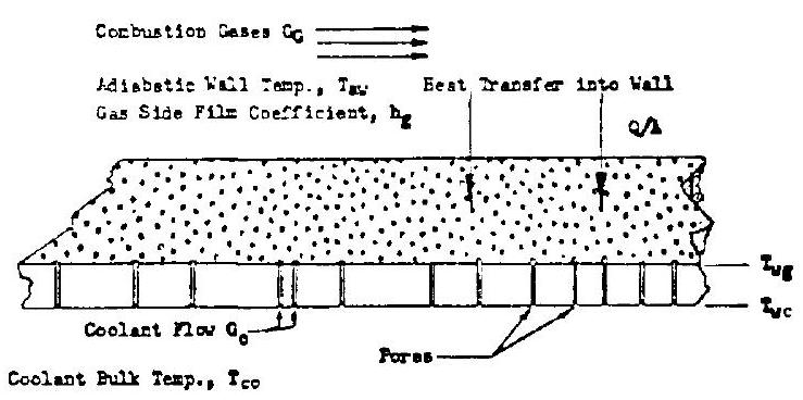 Figure 4-36.-Transpiration cooling model.
Transpiration coolant flow requirements determined from theoretical equations turn out to be significantly lower than those for film cooling. This is due to the more efficient coolant distribution. The Rannie equation for transpiration cooling can be used to calculate the theoretical coolant flow requirements:
where
Test data from various transpiration-cooling experiments have been in good agreement with the Rannie equation. However, the equation predicts coolant flows slightly lower than those required in experiments. It is recommended that an efficiency factor of approximately 0.85 is used for calculations.
The porous material used for the transpirationcooled chamber walls must be selected and dimensioned for correct hydraulic resistance to render the required coolant flow rate per unit surface area. It must also be able to withstand the stresses caused by the pressure differential between coolant and combustion gases, and thermal stresses. These requirements impose certain limitations on the selection of materials and on construction methods. The mechanical design of the coolant distribution system, therefore, is an important factor for successful application of transpiration cooling.
Ablative Cooling
Ablatively cooled thrust chambers have many advantages for upper-stage applications. They are designed to meet accumulated duration requirements varying from a few seconds to many minutes. Most designs are limited to lower chamber pressure applications, 300 psia or less. When assisted by film cooling, or by throat inserts made from refractory materials, successful firings have been made up to a chamber pressure level of 1000 psia . In general, ablative chamber construction is rugged, exterior wall temperatures are held to a minimum and the cost is low.
Ablative cooling is accomplished by the pyrolysis of resins contained in the chamber wall material. The thrust chamber construction will vary with mission requirements. As shown in figure 4-37, chamber and nozzle are composed of an ablative liner, a thin layer of insulation, and a high-strength outer shell. The ablative liner is fabricated from a phenolic-resin-impregnated high-silica fabric which is wrapped in tape form on a mandrel at optimum orientation. The thickness is programed as a function of chamber station to provide adequate strength, charthickness, and minimum weight for a particular mission. A wrap of oriented phenolic-impregnated asbestos is placed on the outer (far) surface of the ablative liner as an insulator.
The high-strength outer shell is composed of layers of unidirectional glass cloth for longitudinal strength, and of circumferential-wound glass filaments for hoop strength. The glass wrap is bonded with epoxy resin. Aluminum alloy and
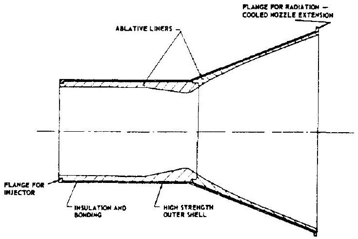 Figure 4-37.-Ablatively cooled thrust chamber.
stainless steel also are sometimes used for the outer shell. The combined thermal resistance of the ablative liner and of the insulation layer protects the outer shell and keeps it at moderate temperatures.
Figure 4-38 shows an ablative-cooled thrust chamber fitted with a throat insert. Both 98 percent tungsten/2-percent molybdenum alloy and pyrolytic graphite have been successfully employed as insert materials. The tungstenmolybdenum alloy has given the best results. Although pyrolytic graphite has a much lower density than tungsten alloy, and therefore has a substantial weight advantage, it is vulnerable to fracture from thermal shock, making design and installation critical. The throat insert is installed with heavy graphite backups for better structural results. Insert and backups are bonded to the thrust chamber main ablative liner with epoxy adhesives. These adhesives have performed satisfactorily up to . Certain ceramic materials, such as silicon carbide, also have been used successfully as throat inserts in space engine applications.
The design of an ablative thrust chamber for a given mission depends on the accuracy of predicting the depth of char during exposure, and on the soak-back temperature variation in the insulation surrounding the charred portion of the thrust chamber wall during and after the hot firing. Test data from hot firings with various ablative thrust chambers indicate that the charring process in the combustion chamber (including throat), that is, the relation between mass pyrolyzed and heat absorbed, can be expressed by the following equation:
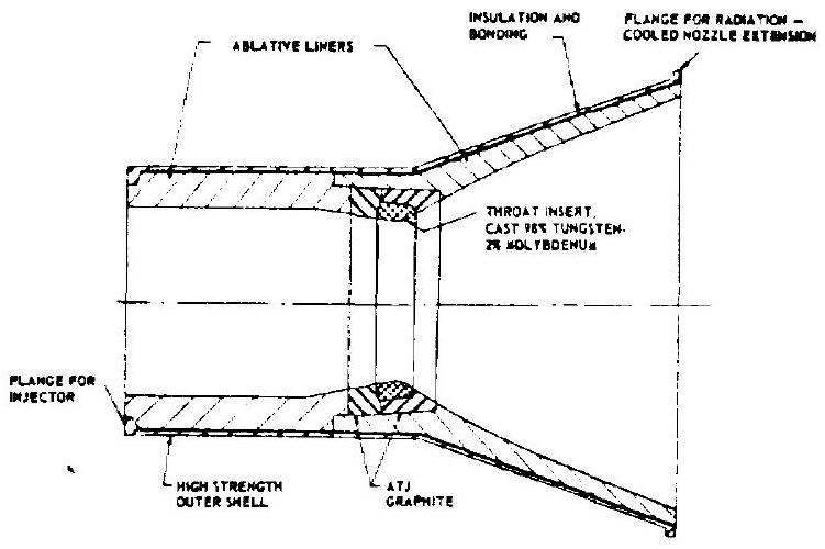 Figure 4-38.-Ablatively cooled thrust chamber with throat insert for high chamber pressure applications.
where
| a | = char depth, in |
|---|---|
| c | = correction factor based on experimental data for the specific design at the throat section, and on a nozzle stagnation pressure of 100 psia |
| = weight fraction of resin content in the ablative material | |
| weight fraction of pyrolyzed resin versus total resin content | |
| = heat capacity at constant pressure of pyrolysis gases, Btu/lb-deg F | |
| p | density of ablative material, |
| heat conductivity of char, deg F/in | |
| thrust chamber firing duration, sec | |
| = latent heat of pyrolysis, Btu/lb | |
| =adiabatic wall temperature of the gas, deg F | |
| =decomposition temperature of resin, deg F | |
| stagnation chamber pressure, psia | |
| They were found to agree very closely with the experimental data. However, for areas down- | Results predicted by equation (4-36) have been compared with char depth data obtained from firings of Refrasil-filled phenolic chambers. |
be somewhat greater than predicted, and when using the equilibrium gas temperature. Temperature recovery in the boundary layer may be one cause for the discrepancy. A modified equation is used, therefore, to predict char depths in the nozzle areas:
where a constant depending upon the nature of the ablative shield (to be determined experimentally) nozzle expansion area ratio at the investigated section base of natural logarithms, 2.718 The char-rate analysis is characterized by physical dimensions and the formation of a char layer that progresses from the heated surface toward the supporting wall. During the pyrolysis of the resin, the formation of a hard carbonaceous surface of increasing thickness is vital because it resists thermal and mechanical ablation and chemical attack. At the charring interface, which slowly travels away from the hot chamber gases, a large amount of heat energy is absorbed by pyrolysis; i.e., melting and vaporization of the bonding material. As gaseous pyrolysis products flow through and out of this char layer, they control the heat flux to the walls by their own endothermic decompositions, and by migration into the boundary layer.
No gross dimensional change occurs due to energy considerations throughout most of the thrust chamber; however, mechanical erosion is evidenced in some designs in the throat region, due to the high prevailing shear stresses. At chamber pressures below 150 psia , throat erosion is generally reduced. Throat erosion rates vary from 0.0005 to
The adaptation of ablative thrust chamber technology to the special field of space engines has been significantly advanced during recent years. Approaches typical for this type of engine will be discussed in chapter XI.
Sample Calculation (4-6)
The following design data are given for the ablatively cooled thrust chamber of the A-4 stage engine:
Determine the char thickness at the throat and combustion chamber section, and in the nozzle at station , after firing for the design duration of 410 seconds.
Solution
From table 3-5: Substitute this and given data into equation (4-36). The char thickness at the throat and combustion section results as:
Char thickness at nozzle station , using equation (4-37):
Radiation Cooling
Cooling by radiation heat transfer is practical only for thrust chamber nozzle extensions, where pressure stresses are lowest. High metal-wall temperatures are required to attain the heat fluxes needed. Assuming negligible temperature drop through the metal and coatings, if any, the steady-state heat transfer for a radiation-cooled nozzle, as shown schematically in figure 4-39, can be expressed by the following correlation:
where
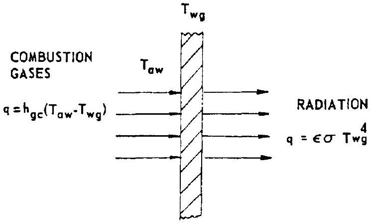 Figure 4-39.-Schematic of radiation cooling.
adiabatic wall temperature of the gas, deg R -side wall temperature = bulk wall temperature, deg R total emissivity of outer wall surface Stefan-Boltzmann radiation heat transfer constant, The design approach to radiation cooling is to determine a value which will satisfy both equation (4-38) and the structural capability of the wall material used under operational conditions.
Only alloys which possess short-time strength in the temperature range of to have been successfully applied to radiation cooling. A molybdenum alloy containing 0.5 percent titanium, and a 90 percent tantalum-10 percent tungsten alloy appear to have sufficient shorttime strength for use at . Because of the low emissivity of molybdenum and also for resistance against oxidation, a coating of is required on both sides of the metal. Titanium alloys and other commercial alloys, such as Haynes 25, have been operated successfully at . If a temperature capability higher than the working range of bare metals is required, insulating coatings of ceramic materials on the gas-side wall surface may be needed. Because of their brittleness and coefficient of thermal expansion relative to that of the alloys, experienced judgment is advised before using these coatings for a specific application.
Sample Calculation (4-7)
The following design data are given for the A-4 stage chamber nozzle extension at station of area ratio : Assuming a total emissivity of 0.95 of outer wall surface, determine the bulk temperature and heat-radiated flux.
Solution
Substitute data into equation (4-37):